THE STORY OF INTAQO

19. 10. 2016

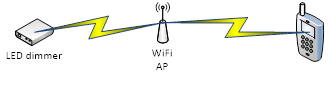
After some struggle, we have come up with the mechanism how to make the connection of the device to the mobile app. It will require implementation of a broadcast protocol, which will search for the devices in the wifi network. Because this is quite low-level programming, which we want to avoid, we have to rely on some existing library. We have decided to use SSDP protocol, for which JT has found a reliable library we can use. We have also verified that there is an implementation of the SSDP for PhoneGap, which is the target platform for the mobile app.

8. 10. 2016

We are progressing with the definition of the system. The architecture is evolving towards a much more user-friendly solution. Instead of connecting requesting the user to connect to the device wifi, we will also allow that the device will connect to home wifi. This way the user will be able to control the

The solution consists of the rmld device and rmld mobile application.

There is a many to many relationship between the components. I.e. one device can be managed via several independent applications and one application can manage several devices.

Connection

The device connects with mobile application via WiFi.

There are 2 modes of operation:

  1. Device connects to existing “home wifi” (also “non-device Wifi”)
    • Mobile application will initiate a SSDP discovery to get the list of available devices with corresponding IP addresses.
  2. Device creates its own WiFi network, to which the phone connects (also “device Wifi)
    • Device will expose the APIs on a fixed IP address.
21.9.2016

We have the following APIs implemented and testable on Apiary:

Friendly name

Operations allow user to set and read name of the device. Name can be changed to allow user to distinguish device between multiple devices.

Discover device

SSDP protocol is used to discover device on network.

Channel count

Firmware version

Signal quality

Internal temperature


Internal temperature measured in RTC module DS3231.

RTC module use temperature to compensate time drift caused by different characteristics of crystal (to be more precise).

Temperature sensor is part of DS3231 and its data are available to connected devices.

Load configuration

Configuration is loaded automatically on startup  or when requested using this operation.

Save configuration

Configuration is saved only when requested using this operation.

Date and time

Date and time stored in device is returned. Device works with local time (time in local time zone) and is not aware of time zones.

19. 9. 2016

JT is making significant progress with the prototype. We are using apiary.io for definition of rest APIs of the device will use. Apiary is allowing us to test these APIs without actually having the device.

Basic principles we follow are these:

API of LED dimmer (next known as device) is based on REST API. API operations use 3 methods:

* GET method for reading values from device

* PUT method for sending values to device

* POST method for executing action in device which does not require input data (e.g. synchronize time from NTP server or save configuration)


Device is considered as a master of values. Therefore all values that can be changed are also exposed via operation for reading.

When sending data to device, it is allowed to send only part of logical block of data (e.g. send only few hours from day when scheduling a day, or set only hour from date time without minutes, seconds, …). In case of sending only partial data, other data which belong to the same logical block are intact (e.g. when only hour during date time setting is sent, only hour will be changed). Data are sent in request body as JSON.


Successfully processed requests are confirmed with http status code 200. Http status code 400 (Bad Request) is used when request cannot be processed (e.g. because invalid input data, incorrect URL parameters). Reponses contain application/json body. This is true for responses to data reading requests and also for responses (both positive with status code 200 and negative with status code 500) to data sending requests.

9. 9. 2016

JT continues to draft the system architecture.

We discussed about the ability of the device to keep time in the case of power outage, so he suggests using DS3231 for this purpose. It is a RTC module (Real Time Clock) which can be battery operated.

It complicates things a little bit (and increases costs) but given the practical side of it, we agree to include it.

4. 9. 2016

The very basic requirements are clear. After thinking a bit about the connection possibilities, there seem to be 3 viable alternatives

Alternative 1 – Direct Wifi connection between mobile and the Dimmer.

Alternative 2 – Both devices are connected to a local wifi network.

Alternative 3 – LED dimmer connects to server, through which it is possible to configure and manage the dimmer.

24. 8. 2016

After a couple of discussions with JT we
draft a plan. He will propose an architecture for the device based on the
ESP8266 and I shall define general requirements on the usability of the system.

JT also suggests adding a DS18B20  based temperature sensor. He has just made a
small temperature gathering prototype he is using at home. The sensor cost
around 1USD per piece so it makes sense to add it to the device.

I have clear idea about the scheduling of
lights during the day. What I want is to be able to freely define schedule for
the day like this:

The specification of the mobile app is taking shape. The largest part of the spec so far is detailed definition of the association flow, which will be a step-by-step initial setup of the device, in which user will choose to either use the device wifi, or to connect to the home wifi and in this case we need to make use of the SSDP discovery.

18. 8. 2016

I contact JT – a colleague from previous work, with whom I had good discussions about electronics and I know he is a tinkerer and likes to play with toys like Arduino. I present him with my problem and suggest it should be possible to create a device according to my needs. To my astonishment, he is very enthusiastic and tells me about ESP8622, an integrated chip module which is sort of Arduino clone and can be very useful as it has integrated Bluetooth and WiFi connectivity. He has this module at home and is able to program it with ease.

After our meeting, I start to do a little research about the chip and the discovery that it costs about 5 USD when purchasing 1+ pieces gets me started. My imagination starts running wild. I imagine creating a remotely managed LED dimmer specific for aquarium lights not just for me, but for everyone who would appreciate the normal, standard features one would expect from a device in the year 2016.

14. 8. 2016

I cannot stop thinking about the dimmer features. Why is it so, that such a poorly designed device costs so much money. I really lack the possibility to remotely control it and also the scheduling is incomprehensible to me. I can define only 2 periods per day during which the lights are on and they have a static ramp-up and fade-out. I would like to let the lights on 10% of intensity for 2 hours in the evening. The aquarium is so beautiful like that (done with the manual dimmer).

I start thinking about making my own dimmer, which will have all these simple features I want to have.

9. 8. 2016

The 2A power sources were not powerful enough to drive both halves of the lamp, so I ended up purchasing a strong enough power source which can give 10A @ 24V.


I ended up with a quite DYI setup, which
I really did not intended when having just invested ~600 EUR into new LED
lights with dimmer.

So instead of being happy and enjoying my
new lights, I am quite frustrated with the whole situation. Why isn’t there a
simple controller, which will enable me to setup a schedule while being
remotely operated? With an application on my mobile phone?